When homeowners ask, “why does my energy storage inverter keep tripping the breaker,” they often expect one simple answer. The reality is more layered. A breaker may trip because of inverter overload, battery charging current, startup surge, ground faults, poor ventilation, or a loose connection. A warm breaker panel, buzzing terminal, or repeated fault code should never be ignored.
The International Energy Agency reported in 2024 that global energy storage capacity may need to expand sixfold by 2030, reaching approximately 1,500 GW. That growth makes reliable inverter installation increasingly important. The U.S. Department of Energy’s Dr. Imre Gyuk has stated, “Energy storage is the key to enabling the electric grid to function with more flexibility and resilience.” His point also exposes a practical weakness: flexibility depends on correct protection settings, cable sizing, and commissioning.
Small details matter. A 30-amp breaker can trip when continuous current remains too close to its rating. A clogged inverter filter can raise internal temperature. An incorrectly configured grid profile may create nuisance trips. Sometimes, the breaker is simply worn. It happens.
This guide examines the most common causes behind repeated trips. It connects manufacturer guidance, electrical safety principles, and field-level troubleshooting. The process is not about repeatedly resetting the breaker. That can hide a developing fault. Instead, readers will learn what to inspect, which measurements require qualified professionals, and when the inverter should remain switched off. Some symptoms overlap, so diagnosis still requires careful testing rather than assumptions.
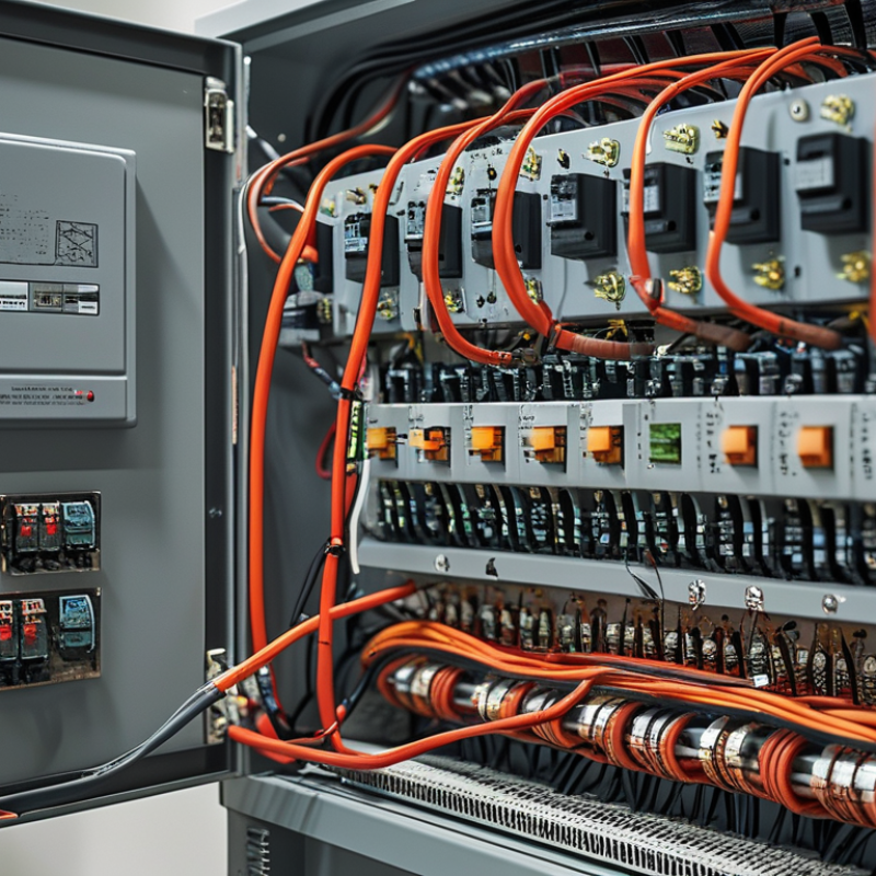
When an energy storage inverter trips a breaker, start with the event log, not guesswork. Record the exact timestamp, phase currents, DC voltage, output power, temperature, and fault code. A thermal overload usually shows sustained current above the breaker rating. An instantaneous trip appears as a sharp current spike with rapid interruption. Ground-fault events may show unequal phase currents or insulation warnings. The distinction matters.
I compare the recorded current and clearing time with the breaker’s time–current curve. Use the correct curve for the installed pole count, frame size, trip unit, and ambient conditions. A current below the curve’s tolerance band may indicate another cause. A current above the instantaneous region can explain immediate opening. Inverter logs often sample too slowly, however. A brief fault may be missed.
During field checks, I inspect terminals for heat marks, loose conductors, and damaged insulation. I also review recent firmware or control-setting changes. Isolate the system safely, then use qualified personnel and approved test equipment. Never defeat protective devices to keep the inverter running. That creates a harder problem.
I have found that people sometimes blame the breaker too early. The breaker may be responding correctly to a poorly coordinated inverter limit. Compare startup current, recharge current, and repeated trips across several operating modes. One imperfect test can mislead the diagnosis, so document each change and restore settings after testing.
| Trip Type | Typical Inverter Log Signature | Breaker or Protection Behavior | Time–Current Curve Indicator | Most Likely Causes | Verification Checks | Recommended Corrective Action | Priority |
|---|---|---|---|---|---|---|---|
| Short-Circuit or Magnetic Trip | “AC overcurrent,” “short-circuit detected,” or instantaneous shutdown. The event normally occurs within a few electrical cycles or immediately after grid connection. | The breaker opens rapidly with little or no delay. The handle may move directly to the tripped position. | For common IEC miniature circuit-breaker instantaneous regions: Type B is approximately 3–5 × In, Type C approximately 5–10 × In, and Type D approximately 10–20 × In. The exact curve must be confirmed from the installed breaker documentation. | Line-to-line fault, line-to-neutral fault, damaged cable, incorrect termination, failed switching device, or an inverter output fault. | Isolate the system, inspect conductors and terminals, test insulation and continuity, check phase-to-phase and phase-to-earth resistance, and compare the logged peak current with the breaker magnetic region. | Do not increase the breaker rating. Repair the wiring or failed component, correct termination torque, verify clearances, and complete commissioning tests before re-energizing. | High |
| Thermal Overload Trip | “AC overcurrent,” “power derating,” or repeated overload warnings. Current remains above the continuous operating level for seconds or minutes rather than rising instantaneously. | The breaker trips after a delay. The trip time becomes shorter when the breaker is already warm or when ambient temperature is high. | The thermal portion of the curve responds inversely to current: a small overload may take a long time, while a larger overload trips faster. Exact limits depend on breaker design, ambient temperature, and installation conditions. | Continuous inverter output above the circuit rating, excessive charging or discharging power, undersized conductors, high ambient temperature, poor ventilation, or multiple loads sharing the same circuit. | Calculate RMS current from logged power and voltage, measure current on all conductors, inspect enclosure temperature, check cable size and installation method, and compare continuous current with the breaker rating. | Reduce or schedule inverter power, separate loads, improve cooling, correct conductor sizing, or redesign the circuit. Any breaker replacement must preserve conductor and equipment protection. | High |
| Residual-Current or Earth-Leakage Trip | “Residual current,” “earth leakage,” “ground fault,” or “insulation resistance low.” The inverter may report leakage during startup, charging, or grid reconnection. | An RCD or RCBO opens even when line current is below the overcurrent rating. The ordinary overcurrent breaker may remain closed. | Residual-current devices operate on the imbalance between outgoing and returning current, not on the normal load current. Common sensitivity values include 30 mA for additional personal protection and higher values for equipment or fire protection, subject to the installation design. | Moisture, damaged insulation, EMC filter leakage, incorrect neutral-earth connections, cable shield faults, DC leakage, or an unsuitable residual-current device type. | Identify the exact protective device, record its residual-current rating and type, test insulation after isolation, inspect for moisture, and measure leakage on each circuit separately. | Remove moisture or damaged wiring, correct neutral and protective-earth routing, confirm compatibility with the inverter’s leakage characteristics, and use only a protection type permitted by the electrical design and local code. | High |
| Inrush or Pre-Charge Trip | “DC-link pre-charge timeout,” “inrush overcurrent,” or “grid synchronization failed.” The trip occurs at energization, after an extended shutdown, or when a contactor closes. | The breaker opens at the instant of connection, while steady-state current may be normal. The problem may disappear after a manual reset or a different startup sequence. | A short, high-current pulse can enter the breaker’s instantaneous region even when the average operating current is acceptable. Breaker curves do not by themselves confirm that the inverter’s inrush is permissible. | Uncontrolled capacitor charging, failed pre-charge resistor, welded or mistimed contactor, repeated rapid restarts, transformer magnetizing inrush, or excessive upstream impedance interaction. | Compare the trip timestamp with contactor and pre-charge events, capture the current waveform with suitable test equipment, inspect pre-charge components, and check the manufacturer-independent system design limits. | Repair the pre-charge circuit, apply the correct startup delay, prevent rapid restart cycling, verify contactor sequencing, and coordinate upstream protection with the measured inrush profile. | High |
| Grid Overvoltage or Undervoltage | “AC overvoltage,” “AC undervoltage,” “grid outside limits,” or repeated grid reconnection attempts. The inverter may disconnect without a corresponding overcurrent event. | The breaker may trip because the inverter or another protective device creates abnormal current during unstable grid conditions, although the breaker itself may not be the original cause. | A standard overcurrent curve cannot diagnose voltage protection. The breaker curve should be reviewed only after voltage magnitude, duration, and current response have been assessed. | Loose neutral, incorrect tap setting, long cable voltage drop, weak grid, excessive local generation, incorrect voltage configuration, or a damaged measurement circuit. | Measure phase-to-phase and phase-to-neutral voltage at the inverter terminals and distribution board, check neutral continuity, compare the event duration with configured limits, and inspect voltage unbalance. | Correct loose connections or configuration errors, reduce voltage drop, coordinate voltage settings with the grid requirements, and investigate the utility or upstream network when abnormal voltage persists. | High |
| Grid Frequency or Anti-Islanding Trip | “Overfrequency,” “underfrequency,” “islanding detected,” “ROCOF,” or “grid loss.” Events often follow a grid disturbance or transfer between operating modes. | The inverter disconnects from the grid. A breaker may open if an external transfer switch, protection relay, or control interlock operates at the same time. | Time–current curves are not the primary diagnostic tool because the initiating condition is frequency or rate-of-change rather than excessive current. | Utility disturbance, incorrect frequency settings, unstable generator output, transfer-switch timing, failed grid relay, or an unintended islanding condition. | Compare inverter logs with utility or site power-quality records, check frequency and phase angle before disconnection, inspect transfer-switch status, and verify relay event records. | Correct transfer sequencing, verify permitted protection settings, repair failed sensing or relays, and do not disable anti-islanding protection to prevent nuisance trips. | High |
| Phase Imbalance or Negative-Sequence Protection | “Phase imbalance,” “negative sequence,” “phase loss,” or “current asymmetry.” One phase may show a significantly different RMS current or voltage. | A three-pole breaker may trip one or more poles after an unbalanced condition. Heating can occur even when the average three-phase current appears acceptable. | Breaker thermal response is affected by the current in each pole and by the device’s multipole characteristics. The total average current alone is insufficient for curve comparison. | Loose phase terminal, open phase, uneven single-phase loads, incorrect phase rotation, unequal cable impedance, or an internal power-stage problem. | Record RMS current and voltage for each phase, verify phase rotation, inspect and torque terminals, check neutral continuity, and compare phase measurements under the same operating power. | Repair the affected phase, rebalance loads, correct phase rotation, replace damaged components, and repeat tests under both charging and discharging conditions. | High |
| Breaker Heating or Loose Connection | Inverter logs may show normal current, but repeated “grid disconnect,” “AC input lost,” or unexplained restart events can occur during high-power operation. | The breaker or terminal becomes hot, may trip after prolonged operation, or may show discoloration or odor. The measured current can remain below the nominal rating. | The published time–current curve assumes specified installation conditions. A loose terminal, high ambient temperature, enclosure crowding, or poor heat dissipation can reduce the practical trip margin. | Insufficient terminal torque, oxidized conductor, damaged breaker contact, undersized cable lug, excessive ambient temperature, or poor enclosure ventilation. | Perform a qualified thermal inspection under load, measure voltage drop across the breaker and terminals, inspect for discoloration, and verify conductor preparation and torque. | De-energize safely, repair or replace damaged connection hardware, follow the specified torque method, improve ventilation, and retest at the intended continuous load. | High |
| Breaker Curve or Protection Coordination Mismatch | No persistent inverter fault may be recorded. The system may trip during high-power transitions, motor starts, transformer energization, or battery charge/discharge changes. | The breaker operates within its normal protection range, but another upstream or downstream device may trip first or trip unexpectedly. | Compare the expected current profile with the complete time–current curves of all protective devices. Review continuous rating, short-circuit rating, instantaneous setting, and selectivity—not only the nominal ampere value. | Incorrect breaker characteristic, poor selectivity, insufficient short-circuit rating, excessive upstream impedance, or protection settings that do not match the inverter operating profile. | Obtain the installed device data, plot measured or calculated current against the curves, check available fault current, and identify which device opened first from auxiliary contacts or event logs. | Have a qualified designer revise protection coordination, select a compliant device, adjust permitted settings, or modify operating limits without exceeding conductor or equipment ratings. | Medium |
| Control, Communication, or Restart-Loop Trip | Repeated “remote stop,” “communication lost,” “BMS shutdown,” “contactor open,” or “restart limit reached.” Current may be normal before the breaker opens. | The breaker may be opened by an external shunt trip, emergency-stop circuit, transfer controller, or repeated restart sequence rather than by overcurrent. | The breaker curve is not applicable if a control circuit intentionally opens the device. Confirm whether the breaker has an undervoltage release, shunt trip, or motor operator. | Intermittent communication, battery-management protection, emergency-stop wiring, unstable auxiliary supply, firmware incompatibility, or a restart loop that repeatedly produces inrush. | Correlate inverter, battery-management, transfer-controller, and breaker auxiliary-contact timestamps. Check auxiliary voltage, control wiring, interlocks, and restart counters. | Repair control wiring or communication, correct interlock logic, stabilize auxiliary power, apply an appropriate restart delay, and verify the emergency-stop function. | Medium |
| Environmental or Installation-Related Nuisance Trip | Trips correlate with heat, humidity, condensation, dust, vibration, or a particular enclosure location. Logs may contain inconsistent or secondary fault codes. | Trip frequency changes with ambient conditions or operating duration. The breaker may reset after cooling, drying, or a period without load. | Breaker reference curves are generally based on specified ambient and installation conditions. Derating may be required for high temperature, grouping, enclosure effects, and continuous loading. | Condensation, contamination, blocked ventilation, excessive enclosure temperature, cable grouping, vibration-induced looseness, or incorrect mounting orientation. | Trend ambient and enclosure temperature, inspect for moisture and contamination, verify ventilation, check mounting and grouping, and repeat measurements under representative conditions. | Seal or ventilate the enclosure as appropriate, remove contamination, correct mounting and cable routing, apply documented derating, and repeat protection tests. | Medium |
: Measure voltage at the battery terminals and inverter input under load. Check both. A large difference may indicate loose connections, cable resistance, or a failing contactor.
Low SOC may trigger undervoltage protection during sudden demand. High SOC may restrict charging and open the BMS contactor.
One cell can reach its voltage boundary while the battery appears healthy. Small deviations matter. Review cell spread, temperature alarms, and current limits.
It provides a safety and performance framework. It does not replace battery protection settings or installation instructions. Coordinate inverter thresholds, BMS limits, and breaker ratings.
Capture voltage, SOC, current, and BMS status during the event. Do not rely only on the inverter event log. The first alarm may mislead you.
Yes. Measure leakage during charging, discharging, and grid-to-backup transfer. Several filters may create accumulated leakage.
No. It is a protection benchmark, not an automatic operating setting. Select the device type according to leakage characteristics and installation instructions.
Use a calibrated RCD tester and record trip current and operating time. Check upstream and downstream discrimination. A neat calculation can still fail on site.
Loose neutral conductors, poor earthing, long cables, and simultaneous loads can affect protection. Recheck the sequence. The breaker may not be the root cause.
If you are asking, “why does my energy storage inverter keep tripping the breaker,” begin by identifying the trip pattern rather than repeatedly resetting the device. Review inverter event logs and compare the timing and duration of the fault with the breaker’s time–current curve. Check whether the inverter’s continuous output current exceeds the system design limit, applying the NEC 125% sizing rule where applicable. This helps distinguish a sustained overload from a short-circuit or protection-coordination issue.
Next, compare the prospective fault current with the breaker’s interrupt rating, expressed in kA, to confirm that the protective device can safely clear the fault. Verify battery voltage, state of charge, temperature, and battery-management-system limits under IEC 62933 guidance, since abnormal operating conditions may trigger shutdowns. Finally, review residual-current protection and coordinate RCD settings, using the IEC 60364 30 mA benchmark where appropriate. If trips continue, have a qualified professional inspect wiring, grounding, connections, and protection settings before restoring normal operation.

 Luzz Solar