When homeowners ask, “why is my smart ems not balancing the battery load,” they usually expect a software explanation. The fault may be simpler. A loose sense wire, inaccurate current sensor, uneven cell voltage, or incorrect balancing thresholds can mislead the energy management system. One cell may reach 4.12 volts while another remains at 3.96 volts. The system then limits charging, even when the battery appears nearly full.
Battery-management specialist Gregory L. Plett states, “Cell balancing is the process of ensuring that all cells in a battery pack have the same state of charge.” This principle guides the checks in this article. We will examine voltage readings, temperature data, communication errors, firmware settings, and balancing activation conditions. A cold battery may refuse balancing. A damaged sensor may report false stability. A weak connection can create confusing numbers.
Small details matter.
Field technicians should compare the EMS display with a calibrated multimeter and the battery manufacturer’s specifications. Do not trust one screen blindly. A reset might remove the warning temporarily, but it may not repair the underlying imbalance. That is an easy mistake to make. We will also consider whether the EMS uses passive balancing, active balancing, or load-sharing logic, because these systems behave differently. The goal is not to force equal readings. It is to identify why balancing never starts, stops too early, or shifts load unevenly. Some cases require professional inspection, especially when swelling, overheating, or damaged wiring appears.
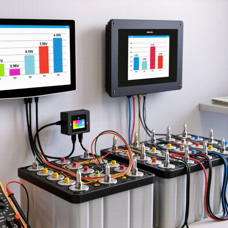
When a Smart EMS fails to balance battery load, the visible symptom is often uneven state of charge. One battery may reach its limit early, while another continues accepting current. The cause is rarely software alone. Begin with measured evidence. Record each module’s voltage, current, temperature, and state-of-charge reading under the same load. A loose terminal, corroded connector, or damaged sensor can distort those readings. Even a small resistance difference creates unequal charging paths.
Configuration errors are common during commissioning. Check battery capacity settings, charge limits, discharge limits, communication addresses, and current-sharing parameters. A mismatched firmware version can also interrupt data exchange between the EMS and battery controllers. Review event logs for repeated communication timeouts or sudden state-of-charge jumps. Do not trust one screen. Compare EMS values with an independent meter and the battery controller display. If temperatures differ sharply, inspect airflow, cabinet spacing, and nearby heat sources.
Load imbalance may also come from aging cells, unequal cable lengths, or one module with higher internal resistance. Run a controlled load test only within permitted operating limits. Watch whether one unit’s voltage falls faster than the others. That pattern often points to cell degradation, not a balancing algorithm fault. In field checks, technicians sometimes replace software before tightening one terminal. That order is not always wise. Document every change, retest under matching conditions, and refer damaged cells to a qualified professional.
| Diagnostic Area | Typical Symptom | Likely Cause | What to Check | Recommended Corrective Action | Expected Result | Priority |
|---|---|---|---|---|---|---|
| Battery State of Charge | One battery rack reaches the charge or discharge limit earlier than the others. | Unequal state-of-charge estimates caused by calibration drift, incomplete charging, or inconsistent operating history. | Compare rack-level state of charge, open-circuit voltage after rest, charge history, and the highest and lowest cell voltage within each rack. | Perform a controlled balancing charge according to the battery manufacturer’s approved limits. Recalibrate the state-of-charge estimate only after confirming accurate voltage and current measurements. | Racks operate within a narrower state-of-charge range and stop limiting the shared load prematurely. | High |
| Cell Voltage Spread | The EMS reports a healthy average voltage, but individual cells show a large voltage difference. | Cell imbalance, weak cells, or a developing high-resistance cell hidden by pack-level averages. | Review minimum and maximum cell voltage, voltage spread under load, and the voltage trend during charging and rest. | Investigate the affected module, verify interconnections, and isolate or replace a confirmed weak cell or module using qualified service procedures. | Reduced cell-voltage deviation and fewer protective cutoffs during high-load operation. | High |
| Temperature Uniformity | A warmer rack supplies less current or reaches thermal limits before neighboring racks. | Uneven airflow, blocked vents, excessive ambient temperature, poor thermal contact, or a faulty temperature sensor. | Compare temperature sensors across racks, inspect airflow paths, check fan operation, and review temperature rise during charging and discharging. | Restore ventilation, remove obstructions, balance airflow, correct sensor placement, and keep operation within the specified temperature range. | More consistent current sharing and fewer temperature-based power restrictions. | High |
| Current Measurement | The EMS shows different charge or discharge currents even when the power path appears parallel. | Current-sensor offset, incorrect sensor scaling, reversed polarity, or inconsistent measurement locations. | Compare EMS current readings with a calibrated meter at several load levels, including near-zero current and rated operating current. | Correct sensor configuration, polarity, scaling, and zero-current offset. Replace a sensor that fails verification. | Accurate current sharing data and more reliable state-of-charge calculations. | High |
| Cable and Busbar Resistance | The closest battery rack carries more current while a remote rack contributes less. | Unequal cable lengths, different conductor sizes, loose terminals, corroded connections, or poor busbar layout. | Inspect torque markings, cable routing, terminal temperature, voltage drop at operating current, and resistance of each parallel path. | Use matched cable lengths and conductor sizes where practical, tighten connections to specified torque, clean approved contact surfaces, and correct the busbar arrangement. | Lower voltage drop and improved current distribution between parallel battery paths. | High |
| Contactor and Fuse Status | A battery rack is visible to the monitoring system but does not deliver or accept meaningful current. | Open contactor, partially engaged switching device, blown fuse, pre-charge fault, or protection lockout. | Check contactor feedback, fuse continuity, pre-charge sequence, rack alarms, and the voltage on both sides of the switching path. | Resolve the protection cause before resetting. Replace a damaged fuse or switching component only with an approved equivalent and verify the pre-charge sequence. | All enabled racks participate in charge and discharge commands without unexpected isolation. | High |
| EMS Control Settings | The EMS repeatedly favors one rack or limits another despite similar voltage and temperature readings. | Incorrect rack priority, current limit, address mapping, control mode, or state-of-charge protection threshold. | Compare configuration files, rack addresses, maximum charge and discharge currents, balancing rules, and enable/disable states. | Restore validated settings, correct rack mapping, and apply consistent current limits. Record the configuration before and after changes. | Coordinated dispatch and consistent participation from all enabled battery racks. | Medium |
| Communication Network | Battery data becomes intermittent, delayed, or inconsistent across racks. | Communication cable damage, incorrect termination, duplicate addresses, grounding noise, or excessive network latency. | Review communication alarms, missing data timestamps, error counters, network topology, termination resistance, and address assignments. | Repair or replace damaged cables, correct termination and addressing, separate communication wiring from high-noise power conductors, and update approved firmware when required. | Stable real-time measurements and fewer incorrect control decisions caused by stale data. | High |
| Battery Age and Capacity | One rack reaches full or empty limits much sooner than newer or less-used racks. | Capacity fade, increased internal resistance, previous high-temperature exposure, or different cycle history. | Compare usable capacity, internal-resistance indicators, cycle counts, full-charge duration, and voltage response at the same current. | Separate mismatched racks where possible, reduce the affected rack’s operating current, and replace modules that fail capacity or resistance testing. | More predictable load sharing and fewer early state-of-charge limit events. | Medium |
| Load Profile | Imbalance occurs only during sudden load changes or high-power events. | Unequal transient response, inverter current-limit behavior, ramp-rate settings, or insufficient control-loop coordination. | Compare rack currents during step loads, inspect inverter ramp settings, and review EMS response time and power-command history. | Coordinate ramp rates, verify inverter limits, tune control response within approved parameters, and avoid abrupt commands that exceed the weakest rack’s capability. | Smoother transient response and reduced short-term current deviation. | Medium |
| Balancing Function | Cell balancing appears enabled, but voltage differences remain after extended charging. | Balancing current is too low for the imbalance, balancing conditions are not met, or the balancing circuit is faulty. | Check balancing start threshold, balancing current, active balancing status, time at balancing voltage, and cell-voltage trend. | Allow sufficient balancing time under approved conditions, verify balancing thresholds, and service a failed balancing circuit or module. | Gradual reduction in cell-voltage spread without exceeding battery operating limits. | Medium |
| Data and Alarm Review | The imbalance is difficult to reproduce and disappears after an EMS restart. | Unlogged transient alarms, stale values, time-synchronization errors, or a software state that does not recover correctly. | Export event logs, alarm history, rack measurements, command history, and synchronized timestamps covering the entire incident. | Capture evidence before restarting equipment, synchronize system clocks, apply approved software corrections, and establish trend logging for voltage, current, temperature, and state of charge. | Faster root-cause identification and reduced recurrence of unexplained imbalance. | Low |
Record each cell’s voltage, temperature, state of charge, and current under identical conditions. Measure the battery when cold. A snapshot can mislead because surface charge may hide weak cells.
Use a controlled discharge test and compare usable capacity with its rated capacity. Log voltage sag and temperature rise. A sharp voltage drop may indicate high internal resistance. Do not guess.
Use a known current limit and confirm constant-current and constant-voltage stages. Record charging time, final voltage, balancing current, and temperature. Charging behavior should match the battery chemistry.
Inspect terminals, fuses, cables, connectors, sensors, and communication signals. Look for heat marks, corrosion, loose terminals, and damaged wiring. Small faults matter.
Confirm charging and discharging limits match the battery specifications. Recalibrate voltage and current readings with a certified meter. Check thresholds, control delays, and communication logs.
Run a supervised charge cycle, then apply a steady load. Monitor cell voltage differences and temperature rise. Confirm balancing current starts at the correct threshold and stops afterward. A widening difference under load needs investigation.
Resting can reveal weak cells hidden by surface charge. Compare the readings before and after rest. One test is not enough. An intermittent fault may appear only after several cycles.
No. A balanced screen can still hide a damaged cell or faulty sensor. Recheck the same measurements under charging, rest, and load. I would not trust one reassuring display.
When asking, “why is my smart ems not balancing the battery load,” begin by identifying whether the issue comes from the battery pack, sensors, wiring, communication signals, or system configuration. Inspect all battery connections for looseness, corrosion, or uneven resistance, and confirm that voltage and temperature sensors are installed correctly and reporting accurate data. Check communication cables, network status, and error messages to ensure the energy management system can receive reliable information from every battery module.
Next, review the Smart EMS settings, including load-balancing limits, charging priorities, voltage thresholds, and current distribution parameters. Test each battery’s health, voltage level, capacity, and charging performance to find weak or mismatched units. After correcting wiring faults, replacing damaged sensors, restoring communication, or adjusting unsuitable parameters, restart the system and monitor its operation under different loads. Confirm that current and voltage are distributed evenly and that no battery is overheating, overcharging, or being excessively discharged. Calibration, firmware updates, and professional inspection may be necessary if imbalance continues.

 Luzz Solar