How to Choose the Right Cable Size for a Solar Inverter

Time:2026-10-07 Author:Liam
0%

Solar power is expanding rapidly, and cable selection is becoming more critical. IRENA’s Renewable Capacity Statistics 2024 reports that global solar capacity reached 1,419 GW by the end of 2023. Every additional installation increases the need for safe, efficient electrical design. A cable is not merely a connection between panels and an inverter. It carries heat, current, and risk.

This guide explains how to select the correct cable size for a solar inverter using practical engineering principles. The process begins with inverter output current, system voltage, cable length, installation method, ambient temperature, and acceptable voltage drop. IEC 62548 provides important guidance for photovoltaic array design, while NEC Article 690 addresses conductor sizing, overcurrent protection, and solar circuit safety in the United States. Local regulations still control the final decision.

Small details matter. A 10-meter cable run in open air behaves differently from the same cable inside a hot conduit. Copper and aluminum also require different calculations and termination practices. Many installers focus only on ampacity. That approach can miss voltage loss and long-term heating. A neat spreadsheet is not enough.

Reliable sizing should include the inverter manufacturer’s specifications, correction factors, continuous-current requirements, and actual site conditions. The SolarPower Europe Global Market Outlook 2024–2028 highlights continued growth in distributed solar, where cable runs can vary greatly between rooftops, garages, and ground-mounted arrays. This makes generic cable charts useful, but never final. Recheck the assumptions. Then verify the result with a qualified electrical professional before installation.
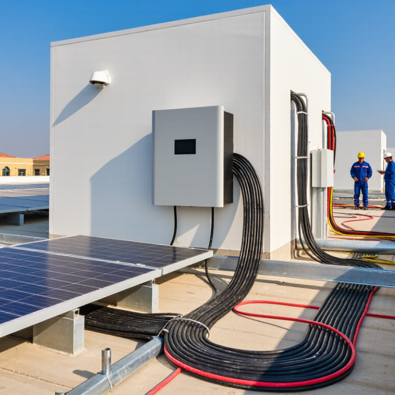
How to Choose the Right Cable Size for a Solar Inverter

Understanding Cable Sizing in Solar Inverter Systems

How to Choose the Right Cable Size for a Solar Inverter

Understanding cable sizing starts with current, distance, temperature, and installation conditions. The inverter’s maximum input current is only one reference point. Designers must also check short-circuit current, cable length, conductor material, insulation rating, and local electrical rules. In many jurisdictions, photovoltaic circuit current is multiplied by 125% for continuous-load calculations. Confirm the required factor locally.

Voltage drop matters. A long cable run can reduce inverter efficiency and create unnecessary heat. NREL’s PVWatts documentation uses 2% as a default assumption for DC wiring losses. However, that figure is a modeling input, not a universal design limit.

Many engineers aim for approximately 1–3% voltage drop, depending on system voltage and project economics. Higher-voltage strings usually carry less current. They may therefore need smaller conductors.

Use the manufacturer’s current data, then verify ampacity under the hottest expected conditions. Cables installed in conduit or grouped tightly may require derating. IEC 62548-1 addresses photovoltaic array wiring, protection, and installation practices, while regional codes define enforceable requirements. A practical check includes measuring the route, not guessing it. A neat spreadsheet is not proof. Real roofs contain bends, shadows, crowded conduits, and hotter surfaces than early drawings suggest. I would also recheck the design after installation, because a small connection error can waste more energy than expected.

Identifying Voltage, Current, and Power Requirements

How to Choose the Right Cable Size for a Solar Inverter

Identify voltage, current, and power before selecting a cable. Power follows P = V × I. A 5 kW inverter at 400 V draws about 12.5 A. At 48 V, it needs roughly 104 A. Lower voltage therefore requires thicker conductors, stronger terminals, and closer attention to heating. Check the inverter’s maximum DC voltage, operating voltage range, and maximum input current. Then compare them with the array’s cold-weather open-circuit voltage and short-circuit current. IEC 62548-1 provides useful guidance for photovoltaic array design and conductor selection.

Cable length changes the answer. Measure the complete circuit path, not only the distance between two devices. A practical voltage-drop calculation uses resistance, current, and conductor length. IEA PVPS Task 13 studies commonly assess low-voltage cable losses near the 1–2% range. NREL’s PVWatts documentation uses a default 2% loss assumption for DC wiring. Treat that figure as a planning reference, not permission to ignore local conditions. NEC-based designs commonly size continuous photovoltaic current at 125% of the calculated maximum, then apply temperature and conduit-fill corrections. My early estimates missed rooftop heat. That mistake matters. A cable rated in cool laboratory conditions may carry less current inside a hot conduit. Verify insulation temperature ratings, connector compatibility, and protective-device limits before installation. Always check the governing electrical code and the manufacturer’s certified terminal range.

How to Choose the Right Cable Size for a Solar Inverter: Voltage, Current, and Power Requirements

Inverter DC Voltage Rated Output Power Estimated DC Input Current
(at 92% efficiency)
Design Current
(125% continuous-load factor)
Recommended Copper Cable Size
(10 m one-way length)
Approximate Voltage Drop Typical Application
12 V 1.0 kW 90.6 A 113.3 A 120 mm² 0.33 V
2.8%
Small off-grid systems, mobile or backup applications
24 V 2.0 kW 90.6 A 113.3 A 70 mm² 0.57 V
2.4%
Medium-sized battery and solar inverter systems
48 V 3.0 kW 67.8 A 84.7 A 25 mm² 1.19 V
2.5%
Residential backup and moderate off-grid systems
48 V 5.0 kW 113.2 A 141.5 A 35 mm² 1.42 V
3.0%
High-power residential and small commercial systems
48 V 8.0 kW 181.2 A 226.5 A 70 mm² 1.13 V
2.4%
Large battery banks and high-demand off-grid systems
Calculation basis: The estimated DC current is calculated as Power ÷ (Voltage × 0.92). Cable sizes are based on copper conductors, a 10 m one-way cable run, a 3% maximum voltage-drop target, and a 125% design-current factor for continuous loads. Actual cable selection must also consider installation method, ambient temperature, cable bundling, insulation temperature rating, short-circuit withstand, fuse or breaker ratings, and applicable electrical codes. Increase the cable size when the cable run is longer than 10 m or when lower voltage drop is required.

Calculating the Correct Cable Cross-Sectional Area

How to Choose the Right Cable Size for a Solar Inverter

Calculating the correct cable cross-sectional area starts with current, not guesswork. The IEA PVPS Trends in Photovoltaic Applications 2024 report recorded more than 400 GW of new solar capacity worldwide in 2023. Larger installations make accurate cable design increasingly important. Use the inverter’s maximum continuous current, not its average operating current. For a 3 kW inverter at 48 V and 92% efficiency, current is about 68 A. The formula is I = P ÷ (V × efficiency).

Cable length also matters. Calculate the complete circuit length, including positive and negative conductors. For an 8-metre one-way run, the circuit length is 16 metres. Using copper resistivity of 0.0175 Ω·mm²/m and a 2% voltage-drop target, the required area is approximately 20 mm². A practical standard size would be 25 mm². Its estimated voltage drop is about 1.6%, before connection losses.

Check the installation conditions afterward. IEC 62548-1 and IEC 60364-5-52 require attention to temperature, grouping, insulation, routing, and protective devices. A cable buried in conduit may carry less current than the same cable in open air. A neat calculation can still be wrong. Real sites contain heat, dust, tight bends, and imperfect terminals. Review the manufacturer’s maximum conductor size and local electrical requirements. Do not guess. Measure twice.

How to Choose the Right Cable Size for a Solar Inverter

The chart uses a 48 V DC inverter system, a 5 m one-way cable run, copper conductors, and a maximum voltage drop of 3% (1.44 V). The calculated cross-sectional area is based on A = ρ × L × I ÷ ΔV, using copper resistivity of 0.0175 Ω·mm²/m and a 10 m total circuit length. The recommended standard sizes are rounded up to commonly available cable cross-sections. Final selection must also verify continuous ampacity, installation method, ambient temperature, and local electrical regulations.

Selecting Cable Materials, Insulation, and Environmental Ratings

Choosing cable size is not only a current calculation. The material and insulation must suit the installation. Copper offers high conductivity and dependable terminations, but it costs more. Aluminum can reduce weight and expense. It needs a larger cross-sectional area and carefully matched lugs. Avoid casual metal mixing. At coastal sites, tinned copper may resist corrosion better. Salt air is unforgiving.

For solar inverter circuits, select insulation rated for outdoor, wet, and high-temperature service. Cross-linked insulation can tolerate rooftop heat and repeated temperature changes. Check its resistance to ultraviolet radiation, ozone, moisture, and abrasion. A cable may look thick, yet its insulation rating can still be inadequate. That detail is easy to miss. Flexible, finely stranded conductors are useful where vibration or tight bends occur, but sharp bends can damage insulation.

Environmental conditions also affect the final cable choice. Measure the temperature inside roof spaces, not only the outdoor air temperature. Apply the correction factors required by local electrical standards. Cables in conduit may need different ampacity calculations from exposed cables. In dusty areas, inspect sealing points regularly. Near soil, water, or metal edges, use suitable protection and maintain clearance. A neat calculation can still mislead if terminal compatibility, voltage drop, and installation length are ignored. Recheck the route before ordering, because real rooftops rarely match the drawing perfectly.

Checking Voltage Drop, Safety Standards, and Installation Limits

How to Choose the Right Cable Size for a Solar Inverter

Cable selection starts with current, distance, and temperature. The IEA PVPS Trends 2024 report recorded more than 400 GW of new solar capacity worldwide in 2023. That growth increases the importance of disciplined wiring design. Calculate the inverter’s maximum current, then apply the required safety factors from the local electrical code. In many jurisdictions, photovoltaic circuits use 125% of short-circuit current for continuous-current calculations. Check the current code edition.

Voltage drop deserves equal attention. Use the complete cable route, including the positive and negative conductors. A common design target is 1.5% to 3% voltage drop, although local rules and equipment instructions may differ. IEC 62548-1:2023 addresses photovoltaic array design, protection, and cable selection. NEC Article 690 provides additional requirements for installations under its jurisdiction. Cable ampacity must also reflect ambient heat, conduit fill, grouping, insulation rating, and rooftop exposure. A cable that passes a simple ampacity test may still run too hot in a crowded conduit. That mistake is easy to underestimate.

Tips: Measure the actual route. Use the manufacturer’s terminal range. Check copper or aluminum compatibility. Leave bending space. Recheck calculations after changing the inverter location. I would also verify every connection torque; rushed terminations remain a common weakness in otherwise careful installations.

FAQS

What current should be used when sizing an inverter cable?

Use the inverter’s maximum continuous current, not its average operating current. For a 3 kW inverter at 48 V and 92% efficiency, current is about 68 A.

How is inverter current calculated?

Use this formula: I = P ÷ (V × efficiency). Here, P means power, V means voltage, and efficiency is written as a decimal.

How should cable length be measured?

Measure the complete circuit path, including both conductors. An 8-metre one-way route becomes 16 metres electrically. Do not measure only one cable.

What cable size suits an 8-metre, 48-volt run?

For about 68 A and a 2% voltage-drop target, the calculation gives roughly 20 mm². A practical standard size may be 25 mm². The estimated drop is about 1.6%, excluding connection losses.

What voltage drop should a solar cable normally allow?

Many designs target about 1.5% to 3% voltage drop. Local rules and equipment instructions may require different limits. Lower is usually better, but larger cables cost more.

Which installation conditions can reduce cable capacity?

Heat, conduit fill, grouped cables, insulation type, and rooftop exposure can reduce ampacity. A cable in a crowded conduit may run hotter than one in open air. The simple calculation is not enough.

What should be checked before connecting the cable?

Confirm the terminal’s permitted conductor range and the local electrical requirements. Check copper or aluminum compatibility. Leave room for bending.

Why should cable connections receive special attention?

Loose or poorly tightened terminals can create heat and voltage loss. Verify connection torque carefully. I might overlook this when focused on cable size. That is a real weakness.

Conclusion

Choosing the correct cable size is essential for a safe, efficient, and reliable solar inverter system. To understand how to select the correct cable size for a solar inverter, begin by identifying the system voltage, maximum operating current, inverter power rating, cable length, and installation conditions. These factors determine the cable’s required cross-sectional area and help prevent overheating, excessive energy loss, and unstable performance.

The cable should be selected with suitable conductor material, insulation, temperature resistance, UV protection, and environmental durability for its installation location. Calculate voltage drop across the full cable run and confirm that it remains within acceptable limits for both the DC and AC sides of the system. Finally, check current-carrying capacity, protective device coordination, local safety standards, bending radius, routing method, and installation limitations. Careful sizing ensures that the cable can handle normal and peak loads while supporting long-term system safety and energy efficiency.

Liam

Liam

Liam is a dedicated marketing professional with a profound expertise in the industry, where he excels at highlighting the unique advantages of our core products. With a keen understanding of market trends and consumer needs, Liam frequently updates our company’s professional blog, providing......